Settings Menu Tab – RESEPI LITE/Ultra LITE

RESEPI User Manual

Settings Menu Tab #

Geometry Tab Window #

The Geometry tab allows you to configure the coordinate system and alignment settings of the IMU and antenna on your payload. The following steps outline the necessary configurations:

Coordinate Axes and IMU Location #
    • IMU Orientation: The coordinate axes of the IMU in the payload are consistent across all RESEPI units, though some units may be rotated. Review the orientation references for specific payloads, as shown in Figure 1:

    • IMU Location: Figure 2 illustrates the IMU’s location inside the payload. Dimensions are provided in millimeters.
Figure_19_LiDAR_Payload_User_Manual_rev_2.6_August_2023_White_Label
Figure 1. Orientation references shown on the Hesai XT-32 payload.
Figure 2. IMU center postion.
IMU to Antenna Offset #
  • Input the antenna’s location relative to the internal IMU using the provided orientation references, as shown in Figure 3. Measure the distance from the IMU to the antenna’s center, adjusting for any antenna positioning that is left, behind, or below the unit. Accurate values are crucial for missions as they influence real-time processing in RTK and recording for PPK. For the best data quality, ensure precision in these measurements.
Figure 3. IMU to Antenna Offset.
Figure 3. IMU to Primary Antenna Offset.
IMU to Secondary Antenna Offset #
  • For a secondary antenna attached, enter the relative location of the second antenna in the “IMU to Second Antenna Offset” section, as shown in Figure 4. Measure from the internal IMU to the second antenna in the right, forward, and up directions.
Figure 4. IMU to Second Antenna Offset.
Figure 4. IMU to Secondary Antenna offset.
Vehicle to IMU Rotation #
  • Input the relative offset angles (axis misalignment) between the IMU and vehicle coordinate axes. This must be done before starting data capture to ensure proper data processing. Adjust yaw, pitch, and roll angles as needed, with values ranging from -180 to 180 degrees. Common configurations include:
    • 0, 0, 0: No rotation needed (Figure 5).
    • 180, 0, 0: 180 degrees rotation in yaw needed (Figure 6).
    • -90, 0, 90: -90 degrees in yaw and 90 degrees in roll needed (Figure 7).
    • 180, -90, 0: 180 degrees in yaw and -90 degrees in pitch needed (Figure 8).
  • For specific orientation queries, please contact RESEPI support
Figure 5. A payload with a “Vehicle to IMU Rotation” of 0, 0, 0. No rotation is needed.
Figure 6. A payload with a “Vehicle to IMU Rotation” of 180, 0, 0. A rotation of 180 in yaw is needed.
Figure 7. A payload with a “Vehicle to IMU Rotation” of -90, 0, 90. A rotation of -90 in yaw and 90 in roll is needed.
Figure 8. A payload with a “Vehicle to IMU Rotation” of 180, -90, 0. A rotation of 180 in yaw and -90 in pitch is needed.
Alignment Settings #
  • Static Time: Set to 5 seconds (recommended) unless the vehicle cannot remain stationary for this period, as shown in Figure 9. This duration is used to estimate gyro biases for data filtering.
  • Kinematic Time: Default is 4 seconds, useful for heading correction.
  • Kinematic Velocity: Defines the velocity requirement for heading correction. Ensure the payload reaches the specified velocity during the “Kinematic Time” to correct heading.
Figure 5. Alignment Settings.
Figure 9. Alignment Settings.
Field of View #
  • Adjust the LiDAR’s field of view to control the default fov data range displayed in PCMasterPro. This setting does not restrict data capture but affects the range of data points populated in PCMasterPro. Default setting is 90 degrees (225-315) for scanners with 360 degree FOV, as shown in Figure 10.
Figure 6. FOV Settings.
Figure 10. FOV Settings.

Connectivity Tab Window #

The Connectivity tab includes settings for wireless networks and RTCM corrections:

  1. Wireless Network Settings

    • Configure the payload to connect to an external Wi-Fi network (WPA/WPA2 Personal networks only). If no network is available, the payload will broadcast its unique Wi-Fi network. Adjust the frequency band based on the drone’s signal: 5 GHz for 2.4 GHz drones and 2.4 GHz for 5 GHz drones. Save the SSID and passphrase, then apply the settings. If the connection fails, the payload will revert to broadcasting its network. To reset the Wi-Fi to its default SSID and passphrase, create a file named “wifi-reset” and save it on the USB drive.

  2. RTCM Corrections

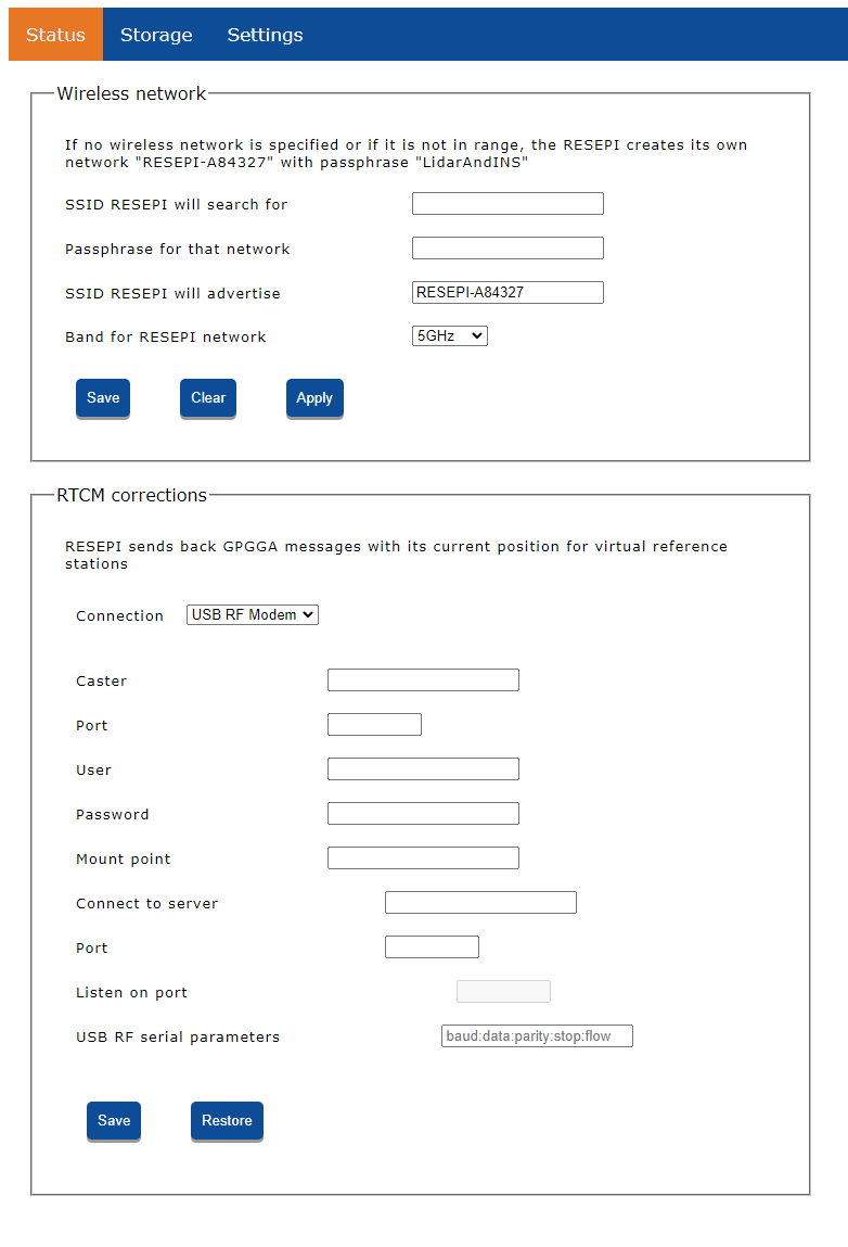
    • In the options for “RTCM Corrections” the user can choose the delivery method for corrections to the payload, as shown in Figure 11. The options are:

      • USB RF Modem like Holybro 915MHz
      • NTRIP Client
      • TCP Server the payload connects to
      • TCP Client connecting to the payload’s pre-defined port.

      Click “Save” to save the changes. The payload will immediately start trying to connect to the selected channel.

      • If “TCP Listen” is selected, the payload will always listen on the port, and once a client connects to the port, the payload will accept the connection.
      • If “USB RF Modem” is selected, the payload will automatically detect connection of a compatible USB RF Modem and open the serial link.
      • If “NTRIP Client” or “TCP Connect” is selected, the payload will keep trying to connect to the specified address until it succeeds.

      Once a connection is established, the payload will start sending its position in a NMEA0183 $GPGGA message, so a virtual reference station can be generated. Real base stations ignore those messages. Once the payload receives RTCMv3 corrections, it will use them to compute RTK position. It will also record the RTCMv3 messages it has received while recording data, so they can be used for post-processing as well.

      Click “Restore” to discard any unsaved changes

Figure 2. RTCM Connection Parameters.
Figure 11. RTCM Corrections Parameters.

Boresight Tab Window #

The Boresight tab allows you to view and update the boresighting alignment and offset values, as shown in Figure 12. Use the “Read from PCMasterPro .pcmp Project” button to load updated values into the system.

Figure 8. The Boresight Information.
Figure 12. The Boresight Information.

Camera Tab Window #

The Camera tab facilitates communication with external cameras and configuration of camera settings, as shown in Figure 13:

  1. Camera Configuration

    • View and modify angular and linear offsets, and calibration parameters. To load new parameters, select “Read from PCMasterPro .pcpp File”.
  2. Trigger Period

    • Adjust the camera trigger period to set the interval between images during data recording. The minimum trigger period is 2 seconds. After saving, the unit will restart, indicated by two camera clicks. Refresh the webpage and select “Reload” to verify new settings.
Figure 9. The Camera Tab.
Figure 13. Camera Information and Parameters.

Firmware Tab Window #

To install firmware updates provided by Technical Support, load the firmware file onto a USB drive, connect it to the payload, and use the “Install” button under the Firmware tab. The unit will install the firmware and reboot. The current firmware version is displayed in the GUI, as shown in Figure 14.

Figure 10. The Firmware Tab.
Figure 14. The Firmware Tab.

INS Service Tab Window #

The INS Service tab is used for direct communication with the GNSS receiver, as shown in Figure 15:

  1. Command and Output

    • Enter commands in the “Command” line and click “Send command” to interact with the receiver. Use “Get more output” button for continuous output from the receiver.
  2. Extended NovAtel Logs

    • From firmware version 4.2.0.0, request additional logs by enabling the Extended NovAtel logs for diagnostics option. This feature is useful for advanced troubleshooting but should be used only if advised by the manufacturer.
    • Additional logs that can now be requested are RXSTATUSB, HWMONITORB, BESTPOSB, RANGEB, ITPSDDETECTB.
  3. Receiver Commands

    • For commonly used receiver commands and additional log descriptions, refer to the provided link.
Figure 15. GNSS Receiver Tab.

LiDAR Service Tab Window #

Configure LiDAR-specific settings using the LiDAR Service tab:

  1. Livox Scanners
    • For Livox scanners such as AVIA, Mid-40, Horizon, and Mid-70, options include (Figure 16):

      • Returns: Select the number of laser returns logged.
      • Scan Pattern: Adjust the scanning pattern (refer to Livox’s LiDAR user manual for details).
      • High Sensitivity: Enhance detection range for small objects with low reflectivity (refer to Livox’s LiDAR user manual for more information).
    • Note that some options may vary by scanner model. It is advisable not to adjust settings without understanding their impact on calibration values.

Figure 16. Additional settings for Livox Avia.

2. Hesai Scanners: 

  • For Hesai scanners like XT32, XT32M2X options such as (Figure 17):
    • Spin Rate: Select the spin rate of the scanner between 300, 600 and 1200. (All units are default boresighted to 600 rpm and changing this setting without correcting the boresight could result in point cloud misalignment).
    • Return Mode: Select the return options from Last, First and Strongest and a combination of them. 
    • Clock source, GPS etc.

The user is not recommended to change any of the lidar settings unless under the supervision of the support from Inertial Labs. Changing these settings can cause problems with data and accuracy.

Figure 12. Lidar Settings Tab.
Figure 17. Additional settings for Hesai Scanners.