Command Line Processing #
PCMasterPro contains a back end processing pipeline that is utilized by different features like One-Click Processing and Batch Processing. It allows for seamless integration into consistent workflows or scenarios where no front end software visuals are needed. Simple scripts can also be built around this tool to utilize the processing power of PCMasterPro without needing to open the software. Currently this feature is only compatible with standard PPK and RTK datasets utilizing an embedded Inertial License.
Please note that this workflow is not recommended for most users. This is for advanced users that desire to expand their workflows and efficiencies and want to utilize PCMasterPro. We highly recommend most users work with PCMasterProGL.
It is important to note the pre-requisites to using this tool. The requirements before stepping into processing include:
- Base station data must be located within the “data” folder of the project loaded
- All items should be located with the .pcmp file loaded
- This includes the full “data” folder, base station data within the “data” folder, and any relevant .pcpp files.
- An active embedded Inertial License through the Local License Manager tool
There are 3 main items when utilizing PCMasterProCL:
- File location of PCMasterProCL.exe
- Typical location is “C:\InertialLabs\PCMasterProGL\PCMasterProCL.exe”
- Project file path
- Ex: “E:\PPK Ultra Lite\ppk.pcmp”
- Optional: a configured .xml profile
- Ex: “E:\PPK Ultra Lite\settings.xml
Let’s dive into each of the following one by one.
PCMasterCL Executable #
This file holds the main processing pipeline for command line processing. It is essential for every single instance of processing command line. It is also very important to always ensure the latest version of PCMasterPro is installed to utilize these features.
Project File Path #
The second item is the project input path. This is the basis of the configuration of how the dataset will be processed. This file contains an xml type formatting with items like cloud filters, trajectory selection, trajectory file paths, base station file paths, etc. Projects configured correctly from the RESEPI GUI will be setup automatically to utilize those processing settings. It is important to note that not all of the project settings are held within this file, which is why some workflows will require the .xml file.
Formatting of this file will look similar to what is found below. RTK datasets appear to be very similar, but are lacking the <base path> field. Different lasers and hardware configurations will show different results. It is not recommended to edit this file as it determines the full direction of processing. Settings that are wanting to be changed should be done within the .xml file.
					<?xml version="1.0" encoding="UTF-8"?>
<Project>
    <Files>
        <data path="data/RESEPI-2025-08-15-14-19-19-001.data"/>
        <data path="data/RESEPI-2025-08-15-14-19-19-002.data"/>
        <data path="data/RESEPI-2025-08-15-14-19-19-003.data"/>
        <data path="data/RESEPI-2025-08-15-14-19-19-004.data"/>
        <data path="data/RESEPI-2025-08-15-14-19-19-005.data"/>
        <data path="data/RESEPI-2025-08-15-14-19-19-006.data"/>
        <data path="data/RESEPI-2025-08-15-14-19-19-007.data"/>
        <data path="data/RESEPI-2025-08-15-14-19-19-008.data"/>
        <data path="data/RESEPI-2025-08-15-14-19-19-009.data"/>
        <data path="data/RESEPI-2025-08-15-14-19-19-010.data"/>
        <trajectory path="ins/ppk.txt" ppk="1">
            <rover path="ins/RESEPI-2025-08-15-14-19-19-gnss.gps"/>
            <imu path="ins/RESEPI-2025-08-15-14-19-19-imu.imr"/>
            <base path="data/basefile"/>
        </trajectory>
    </Files>
    <Selection>
        <path start="0" finish="2147483647" display="1" export="1"/>
        <laser number="0" display="1" export="1"/>
        <laser number="1" display="1" export="1"/>
        <laser number="2" display="1" export="1"/>
        <laser number="3" display="1" export="1"/>
        <laser number="4" display="1" export="1"/>
        <laser number="5" display="1" export="1"/>
        <laser number="6" display="1" export="1"/>
        <laser number="7" display="1" export="1"/>
        <laser number="8" display="1" export="1"/>
        <laser number="9" display="1" export="1"/>
        <laser number="10" display="1" export="1"/>
        <laser number="11" display="1" export="1"/>
        <laser number="12" display="1" export="1"/>
        <laser number="13" display="1" export="1"/>
        <laser number="14" display="1" export="1"/>
        <laser number="15" display="1" export="1"/>
        <laser number="16" display="1" export="1"/>
        <laser number="17" display="1" export="1"/>
        <laser number="18" display="1" export="1"/>
        <laser number="19" display="1" export="1"/>
        <laser number="20" display="1" export="1"/>
        <laser number="21" display="1" export="1"/>
        <laser number="22" display="1" export="1"/>
        <laser number="23" display="1" export="1"/>
        <laser number="24" display="1" export="1"/>
        <laser number="25" display="1" export="1"/>
        <laser number="26" display="1" export="1"/>
        <laser number="27" display="1" export="1"/>
        <laser number="28" display="1" export="1"/>
        <laser number="29" display="1" export="1"/>
        <laser number="30" display="1" export="1"/>
        <laser number="31" display="1" export="1"/>
    </Selection>
    <Filters>
        <range min="8.000" max="200.000"/>
        <rotation min="2.25" max="3.15"/>
    </Filters>
    <Offsets>
        <priAnt x="0.0000" y="0.0000" z="0.0000"/>
    </Offsets>
</Project>
XML Settings File #
The file that holds the true power of PCMasterCL is the .xml settings file. This file contains all of the configurable settings within PCMasterGL and can be pre-configured within this .xml to utilize over the course of CL processing.
If a user decides to run PCMasterCL without utilizing an xml file (only CL exe and .pcmp paths), then processing will default to standard settings produced by the One-Click Processing method.
The configurable settings within the .xml include:
- Export:
- <batch> — true / false
- Enables this xml processing mode, which triggers automatic processing of the project. Set to true for command-line use; false would skip processing.
- <noColor> — true / false
- Exports a point cloud without RGB color (intensity/reflectivity data only). Set to true to produce a standard LiDAR-only output.
- <color> — true / false
- Exports a point cloud with RGB colorization applied from camera images. Only relevant for projects that include a camera (CAM projects); ignored otherwise.
- <colorizationQuality> — Standard / High
- Colorizes the point cloud using the selected pipeline – one that prioritizes speed and one that prioritizes quality.
- <expByPath> — true / false
- Controls whether the export is split into separate files per scan path (true) or merged into a single combined output file (false). All projects are configured with the entire trajectory unless selected and saved in PCMasterProGL.
- <exportLAS> — true / false
- Outputs the point cloud in uncompressed .las format. If both exportLAS and exportLAZ are true, both formats are kept.
- <exportLAZ> — true / false
- Compresses the output to .laz format. If exportLAS is false, the intermediate .las file is deleted after compression.
- <additiveColorization> — true / false
- Utilizes this tool in order to provide an enhanced level of colorization through calculated estimations of nearest neighbors.
- <K> (under Export) — integer (e.g. 10)
- The number of nearest-neighbor camera pixels used when colorizing each LiDAR point. Higher values sample more images for smoother color blending but are slower. Only used when blending is on.
- <blend> — true / false
- Applies a blur/blending effect to the camera cloud colors to reduce sharpness
- <batch> — true / false
- Trajectory:
- <selectAllPaths> — true / false
- When true, ignores any flight path selections saved in the project and processes the entire trajectory from start to finish. Setting to false only matters if paths are pre-selected and entered into the project file.
- <profile> — 0, 1, 2, 3, or 4
- Sets the GNSS/IMU processing profile optimized for the platform type:
- 0 = Automatic Detection
- 1 = UAV
- 2 = Airborne
- 3 = Ground Vehicle
- 4 = Marine
- 5 = Pedestrian
- Sets the GNSS/IMU processing profile optimized for the platform type:
- <frequency> — 0, 1, or 2
- Sets the GNSS processing rate:
- 0 = Automatic
- 1 = 20 Hz
- 2 = 1 Hz
- Sets the GNSS processing rate:
- <refine> — true / false
- Enables automatic lever arm refinement, where the software fine tunes the IMU-to-antenna offset using the data itself to improve accuracy. Lock for specific applications.
- <Primary x=”…” y=”…” z=”…”/> — decimal meters
- The physical offset (lever arm) from the IMU to the primary GNSS antenna, in the sensor body frame. X = forward/backward, Y = left/right, Z = up/down, all in meters. Leaving blank will use “0” for value input.
- <Secondary x=”…” y=”…” z=”…”/> — decimal meters
- Same as Primary, but for the secondary GNSS antenna (used in dual antenna setups for heading). Leave blank if not applicable.
- <selectAllPaths> — true / false
- Coordinate Systems:
- <horizontal> — string (e.g. “EPSG:32632”)
- The target horizontal coordinate reference system for reprojection. Leave empty to use the project’s default.
- <vertical> — string (e.g. “EPSG:5703”)
- The target vertical datum for reprojection (e.g. an ellipsoidal or geoid height system). Leave empty to use the project’s default.
- <horizontal> — string (e.g. “EPSG:32632”)
- Base Station:
- <x>, <y>, <z> — decimal coordinates
- The known position of the GNSS base station. X and Y are typically easting/northing or longitude/latitude in the project’s CRS; Z is ellipsoidal height in meters. Leave empty to use the position stored in the base station file.
- <antennaOffset> — decimal meters
- The height of the base station antenna above the ground mark (ARP height). Added to Z when computing the true antenna phase center height.
- <arpApcOffset> — decimal meters
- The offset from the Antenna Reference Point (ARP) to the actual phase center of the antenna. Provided in antenna calibration specs. Sometimes read automatically from base file.
- <useAntennaOffset> — true / false
- Whether to apply the antennaOffset and arpApcOffset corrections. Set to false if your base station Z coordinate already accounts for antenna height.
- <x>, <y>, <z> — decimal coordinates
- Outlier Removal:
- <enabled> — true / false
- Runs statistical outlier removal on the point cloud before export to remove noise and isolated points.
- <K> (under Denoiser) — integer (e.g. 10)
- The number of nearest neighbors analyzed per point when detecting outliers.
- <sigma> — decimal (e.g. 5.0)
- The standard deviation threshold for outlier rejection. Points whose mean neighbor distance is more than this many standard deviations above the global mean are removed. Lower values are more aggressive.
- <enabled> — true / false
- Filters:
- All filters share the same attributes: enabled=”true/false”, min=”…”, max=”…”.
- Only points within the [min, max] range pass through when enabled.
- <Distance> — meters
- Filters by the raw LiDAR range (distance from the sensor to the return). Useful for removing close-range noise (e.g. keep min=”8.0″) or far-range noise.
- <AngularRate> — degrees per second
- Filters by the sensor’s rotation rate at the time of each shot. Can be used to exclude points captured while the platform was maneuvering sharply.
- <Azimuth> — degrees (0–360)
- Filters by the horizontal scan angle of the LiDAR beam. Useful for masking specific directions, e.g. excluding returns directly beneath the aircraft or behind a sensor blind spot.
- <Reflectivity> — unitless scale (0–100)
- Filters by the intensity/reflectivity of each return. Can remove very low-reflectivity returns (noise) or very high ones (retroreflectors).
- <CoordinateX> — projected meters (Easting)
- Filters by the final projected X (Easting) coordinate of each point. Useful for clipping output to a geographic region.
- <CoordinateY> — projected meters (Northing)
- Filters by the final projected Y (Northing) coordinate of each point.
- <CoordinateZ> — meters (Altitude/Elevation)
- Filters by the final Z (elevation) coordinate. Useful for removing ground or above-canopy points outside a known height band.
- <TimeOfWeek> — seconds (0–604800)
- Filters by GPS Time of Week — the number of seconds since the start of the current GPS week. Allows processing only a specific time window within the flight.
- All filters share the same attributes: enabled=”true/false”, min=”…”, max=”…”.
An example of what the xml formatting should be can be found below. Below also shows the recommended starting point for settings to process with when using the xml. It’s recommended to start with this as the baseline and edit only as needed.
					<?xml version="1.0" encoding="UTF-8"?>
<PCMasterSettings>
    <Export>
        <batch>true</batch>
        <noColor>true</noColor>
        <color>true</color>
        <expByPath>false</expByPath>
        <exportLAS>true</exportLAS>
        <exportLAZ>false</exportLAZ>
        <K>10</K>
        <blend>false</blend>
    </Export>
    <Trajectory>
        <selectAllPaths>true</selectAllPaths>
        <profile>0</profile>
        <frequency>1</frequency>
        <refine>true</refine>
	    <Primary   x="0.0" y="0.0" z="0.0"/>
        <Secondary x="0.0" y="0.0" z="0.0"/>
    </Trajectory>
    <CoordinateSystem>
        <horizontal></horizontal>
        <vertical></vertical>
    </CoordinateSystem>
    <BaseStation>
        <x></x>
        <y></y>
        <z></z>
        <antennaOffset>0.0</antennaOffset>
        <arpApcOffset>0.0</arpApcOffset>
        <useAntennaOffset>true</useAntennaOffset>
    </BaseStation>
    <Denoiser>
        <enabled>false</enabled>
        <K>10</K>
        <sigma>5.0</sigma>
    </Denoiser>
    <Filters>
        <Distance     enabled="true" min="8.0"       max="1000.0"/>
        <AngularRate  enabled="false" min="0.0"       max="8.0"/>
        <Azimuth      enabled="false" min="0.0"       max="360.0"/>
        <Reflectivity enabled="false" min="0.0"       max="100.0"/>
        <CoordinateX  enabled="false" min="-20000000" max="20000000"/>
        <CoordinateY  enabled="false" min="-20000000" max="20000000"/>
        <CoordinateZ  enabled="false" min="-200000"   max="200000"/>
        <TimeOfWeek   enabled="false" min="0.0"       max="604800.0"/>
    </Filters>
</PCMasterSettings>
RTK datasets are configured very similar to PPK datasets when looking at the XML. All settings are identical with the removal of some that are not applicable, especially when looking at trajectory processing. Below is a foundation of default settings of an RTK XML profile. If a different profile is used with an RTK dataset, those values may be ignored, as they are not applicable.
					<?xml version="1.0" encoding="UTF-8"?>
<PCMasterSettings>
    <Export>
        <batch>true</batch>
        <noColor>true</noColor>
        <color>true</color>
        <colorizationQuality>Standard</colorizationQuality>
        <expByPath>false</expByPath>
        <exportLAS>true</exportLAS>
        <exportLAZ>false</exportLAZ>
        <exportPCD>false</exportPCD>
        <exportPLY>false</exportPLY>
        <exportE57>false</exportE57>
        <additiveColorization>false</additiveColorization>
        <K>10</K>
        <blend>false</blend>
    </Export>
    <Trajectory>
        <selectAllPaths>true</selectAllPaths>
    </Trajectory>
    <CoordinateSystem>
        <horizontal></horizontal>
        <vertical></vertical>
    </CoordinateSystem>
    <Denoiser>
        <enabled>false</enabled>
        <K>10</K>
        <sigma>5.0</sigma>
    </Denoiser>
    <Filters>
        <Distance     enabled="true" min="8.0"       max="1000.0"/>
        <AngularRate  enabled="false" min="0.0"       max="8.0"/>
        <Azimuth      enabled="false" min="0.0"       max="360.0"/>
        <Reflectivity enabled="false" min="0.0"       max="100.0"/>
        <CoordinateX  enabled="false" min="-20000000" max="20000000"/>
        <CoordinateY  enabled="false" min="-20000000" max="20000000"/>
        <CoordinateZ  enabled="false" min="-200000"   max="200000"/>
        <TimeOfWeek   enabled="false" min="0.0"       max="604800.0"/>
    </Filters>
</PCMasterSettings>
How to Run #
To run this within command line, the user will simply need to open a new instance and run the following:
"C:\InertialLabs\PCMasterProGL\PCMasterProCL.exe" "<project_file_path>" "<xml_file_path>"
An example input would be:
"C:\InertialLabs\PCMasterProGL\PCMasterProCL.exe" "D:\IL\DA MMS with RINEX Base\ppk.pcmp" "D:\IL\DA MMS with RINEX Base\default_settings.xml"
To clarify, if the user would just like to use all standard default values, then they may remove the xml location to give the input such as:
"C:\InertialLabs\PCMasterProGL\PCMasterProCL.exe" "<project_file_path>"
An example input with no xml would be:
"C:\InertialLabs\PCMasterProGL\PCMasterProCL.exe" "D:\IL\DA MMS with RINEX Base\ppk.pcmp"
Once this command is run, the user will begin to observe processing begin. All standard messaging from the PCMasterGL status tab will show in the command prompt. Messages will show to help indicate if any pre-requisites are missing (base station data or licensing). Once finished, the user will see an exit code (either 0 or 1) indicating success or failure.
Once finished, a report will be generated within the “ins” folder called “CL-Processing-Settings-YYYY-MM-DD-HH-MM-SS.html”. This report shows the pushed settings into the pipeline is an easily understandable format. This report isn’t anything more than the information already given within the xml profile. Other standard post processing and cloud reports are still generated as well.
Command Line License Activation #
If needing to activate a waypoint license through command line, the instructions below are given through the following command.
C:\InertialLabs\PCMasterProGL>LLMform.exe -h
					LLM Console - Local License Manager
	Copyright NovAtel Inc. 2026

Usage:
LLMForm	[-h]
		[-a "ActivationID" "ActivatorInfo"]
		[-r "ActivationID"]
		[-e "ActivationID"]
		[-am "ActivationID" "ActivatorInfo" "outputfilename"]
		[-rm "ActivationID" "outputfilename"]
		[-p "inputfilename"]
		[-v]
		[-l]

Where,
  -h		View help
  -a		activate license with ActivationID and optional ActivatorInfo
  -r		return license with ActivationID
  -e		enable a disabled license with ActivationID
  -am		activate manually license with ActivationID and optional ActivatorInfo. (No internet connection)
  -rm		return manually license with ActivationID.  (No internet connection)
  -p		Process input file.  (No internet connection)
  -v		view licenses
  -v		view recently returned licenses


Return Values and Error Handling,
	Written to the xml file %APPDATA%\NovAtel\LLM\LLMReturn.xml
	Format of the xml file

	<LLMReturn>
		<LastOperation>OPERATION<\LastOperation>
		<ReturnValue>TRUE<\ReturnValue>
		<ErrStr>""<\ErrStr>
		Note if the last operation was View licenses, each license will be displayed as follows
		<License>
			<Name>NAME=Inertial Explorer SDK;VERSION=8.40</Name>
			<ActivationID>1234-1234-1234-1234-1234-123</ActivationID>
			<FulfillmentID>FID__1234567_1234567890__1234</FulfillmentID>
			<Expiration>30-May-2012</Expiration>
		</License>
	<\LLMReturn>

	Where,
	OPERATION - last operation used with console. Possible values,
		Activate
		Return
		View
		ViewReturned
	ReturnValue - true if successful. False see ErrStr
	ErrStr - if Return is FALSE ErrStr will be present
Below shows an example of what the user would enter to active and return a license key.
C:\InertialLabs\PCMasterProGL>LLMform.exe -a 1234-1234-1234-1234-1234-123
C:\InertialLabs\PCMasterProGL>LLMform.exe -r 1234-1234-1234-1234-1234-123
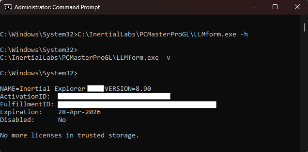
Similar information can be seeing by using a “-v” entry to view license information like what is observed in the screenshot below.