
Definition of Main Menu Items #
General Settings Caution #
Adjustments to settings such as Lasers, Angular and Linear Offsets (LiDAR and Camera), and Camera Calibration should only be made by trained users or under the guidance of customer support as they related to the boresight of the unit and changing them will affect the various boresight calibrations.
File menu #
- New Project: The New Project File menu item clears the window of any currently loaded data and asks for the new trajectory and scan files. The new data will be loaded, and the trajectory will be displayed after processing (PPK only). Calibration values and offsets are taken from the LiDAR scan files; any filters are cleared to their preset defaults.
- Open Project: The “Open Project” option replaces the current data with a newly selected project, loading its trajectory, scans, and any saved paths automatically. Calibration values, offsets, and filters are also retrieved from the project file.
- Save Project: The Save Project File menu item saves the current state of the project to the project file.
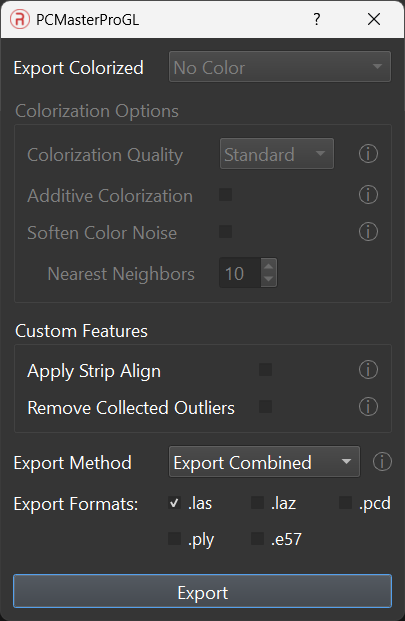
- Export LAS File(s): The “Export LAS File(s)” function generates LAS files from the point cloud, using data from selected lasers and points enabled by cloud filters. Before exporting, the project is automatically saved. Options available for export include:
- Export Colorized: Choose between uncolorized and colorized point clouds.
- Colorization Options: Available when the colorized option is selected, offering colorization qualities, additive colorization, and blending tools for a uniform colorized point cloud.
- Qualities offer 2 options for balancing color accuracy and detail and processing time.
- Additive colorization utilizes surfaces and nearest neighbors to estimate the colors of uncolorized points.
- Soften color noise reduces the static effect in some images, providing a smoother color fade.
- Custom Features: Allows the application of StripAlign and noise filter options.
- Remove Collected Outlier: The Remove Collected Outlier option must only be checked after the Remove Statistical Outlier tool has been run to find the outliers in the dataset. This option works independently from the “Remove Outliers from Visualization” option in the Remove Outliers Tool. This option must be checked to export the point cloud without the identified outliers.
- Export Method: Choose to export paths as a single combined point cloud or as separate paths.
- Export as File Type: Option to export in .las, .laz, .pcd, .ply, or .e57 format.
Data Selection #
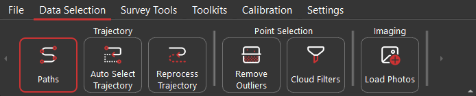
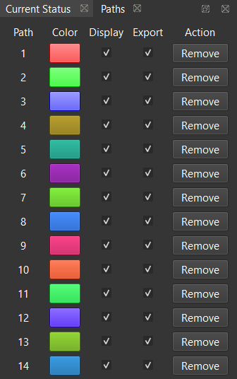
- Paths: Lists available trajectory segments with display colors. Paths can be toggled for display and export or removed, as shown below.
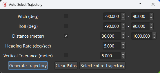
- Auto Select Trajectory: Assists in selecting paths based on specified criteria such as pitch, roll, distance, heading rate, and vertical tolerance. Default values are provided for common flight plans.
The fields within this window are described below:
- Pitch adjusts the window of allowed pitch orientation (in degrees) along the trajectory.
- Roll adjusts the window of allowed roll orientation (in degrees) along the trajectory.
- Distance adjusts the minimum and maximum length a path should be (in meters) before it’s selected.
- Heading Rate limits paths from the trajectory that contain quick movements with yaw by using the entered value as the maximum accepted rate (in degrees per second).
- Vertical Tolerance limits the selected paths to a specific altitude. If the maximum altitude of the path minus the minimum altitude of the path exceeds the entered vertical tolerance, the path will not be selected.
- Generate Trajectory, when selected will automatically highlight the paths that meet the criteria entered above and populate the visualizer for each path.
- Clear Paths will delete all selected paths.
- Select Entire Trajectory will select the default path which encompasses the entire recording time.
- Reprocess Trajectory: Enables users to reprocess a trajectory after making changes like updating base station files.
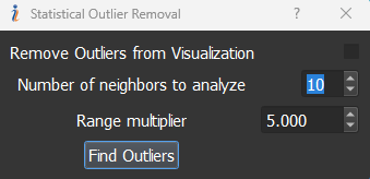
- Remove Statistical Outlier: Remove Statistical Outlier allows the user to identify remove noise from the point cloud, as shown below. Users can change the tolerances to correctly identify the points that are part of the noise and remove them from both visualizer and the exported point cloud. To remove the identified points from the visualizer, User needs to check the option “Remove Outliers from Visualization” and to export a point cloud with the noise removal filter, User needs to check “Remove Collected Outliers” option in the Export menu.
Number of Neighbors to analyze takes input (of values more than 1) of how many neighbors of each point must be scanned to be within a certain statistical bound. The larger the number the more processing time it takes as it must go over more points per iteration.
Range Multiplier takes input (in increments of 0.1) of how many standard deviations of the average distance between the number of neighbors being scanned through, are allowed.
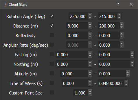
- Cloud Filters: Opens a panel for configuring filters to visualize the point cloud accordingly, as shown below. Available filters include:
- Rotation angle filter: filter restricts the cloud to points obtained from lidar when its reported rotation angle is between the minimum(0 degrees) and the maximum value (360 degrees).
- Distance filter: filter restricts the cloud to points within a certain distance range from the LiDAR in meters. This is useful for filtering out reflections from the car roof by setting the left value to some 2 meters and the right to some insanely large value.
- Reflectivity filter: filter restricts the clouds to points within a certain reflectivity range.
- Angular rate filter: filter restricts the clouds to points taken when the LiDAR payload was turning slower than the set value in degrees per second.
- Easting, Northing, and Altitude filters: These filters simply reject points that are outside the set boundaries in meters.
- Time of Week (s) filter: It does not populate points in the main window that are outside the set boundaries entered in seconds, based off the GPS Time of Week.
- Custom Point Size: Allows the user to scale up or down the size of all points in the main window, the default size is 1
- Load Photos: Load the photos from the camera folder into the current project. If user attempts to export the colorized point cloud prior to loading the photos, PCMasterPro will automatically load the photos for export.
Survey Tools #
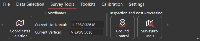
- Coordinates: The Coordinates menu in PCMasterPro allows users to reproject point clouds into a desired geoid or coordinate system. By default, PCMasterPro projects point clouds using the WGS 84 ellipsoid and UTM coordinate system. This new feature replaces the earlier GEOIDS option found in PCMasterPro v1.4.0.0 and earlier versions, offering expanded options for reprojection, including both horizontal and vertical systems.
Steps to Reproject a Point Cloud:
Open Project: Open the
ppk.pcmpfile and load the project in PCMasterPro.Access Coordinates Menu: Navigate to Tools and select Coordinates Menu.
Select Coordinate Systems: In the available coordinates dialogue box, select the desired coordinate systems, as shown below. Only systems applicable to the location where the dataset was captured will be available. Choose the desired horizontal and vertical models from the respective tabs. The selected models will appear in the New Horizontal Model and New Vertical Model fields. You can search for models by typing part of the model names or their EPSG numbers. The Current Model field will display the model currently used for the point cloud.
Reproject the Point Cloud: Click the Reproject button to begin the conversion process.
Verify Output: If the reprojection is successful, a new trajectory file will be saved in the
convertedTrajectoriesfolder. This folder will also contain an information file detailing the coordinate systems used.
Note: Some coordinate systems require grid files in .tif format. If you attempt to convert to such a system without these files, PCMasterPro will display an error. Ensure you have the necessary grid files, which can be acquired and placed in the
/projfolder within the PCMasterPro installation directory. A common resource for obtaining these grid files is https://cdn.proj.org/.For example to Reproject in NAD83(2011) in Geoid 18, you would need to download and place these two grid files in your /proj folder
- us_noaa_g2018p0.tif – USA – Puerto Rico and the Virgin Islands – NAD83(2011) (EPSG:6319) to PRVD02 height (EPSG:6641). Last modified: 2020-01-24
- us_noaa_g2018u0.tif – USA – Conterminous – NAD83(2011) (EPSG:6319) to NAVD88 height (EPSG:5703). Size: 16.0 MB. Last modified: 2020-01-24
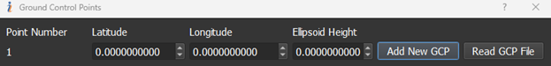
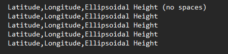
- Ground Control Points: Allows users to input surveyed Ground Control Points (GCPs), displayed as white stars or plus signs in the point cloud. The positions of these points can be entered in the Ground Control Point menu as shown below. GCPs can be added manually individually or as a group via a text file. If trying to add GCPs with a text file, the file should follow the specific format as seen in the figure below. If using a text file, please make sure to name the file something other than “gcp.txt” as GCPs are stored to project folders with this name in the “gcp” folder.
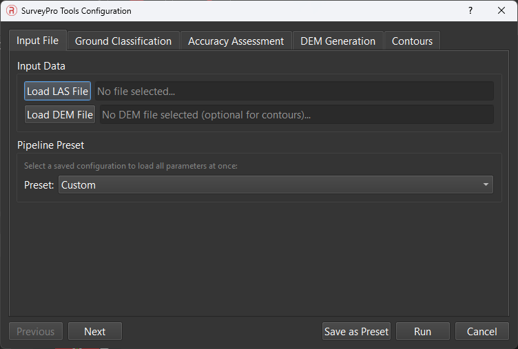
- SurveyorPro Tools: This pop-up window is exclusive for users with SurveyorPro licenses activated through the PCMasterProGL Licensing menu. This menu offers items like ground/non-ground classification, GCP to cloud accuracy assessments, manual and automated debiasing, DEM generation, and Contour creation. For more information on window specifics and breakdowns, navigate to SurveyorPro Tools.
Toolkits #
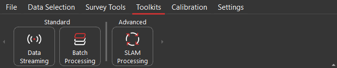
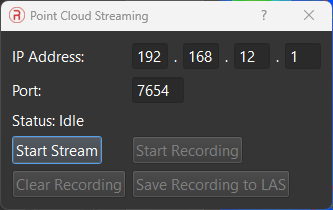
- Data Streaming: This is designed for mobile mapping scenarios and setup for future development with long range point cloud streaming. The host computer can connect to the IP address of the payload using either the Wi-Fi or Ethernet IP. Port can usually be left as default. Streams can be visualized, recorded, and saved.
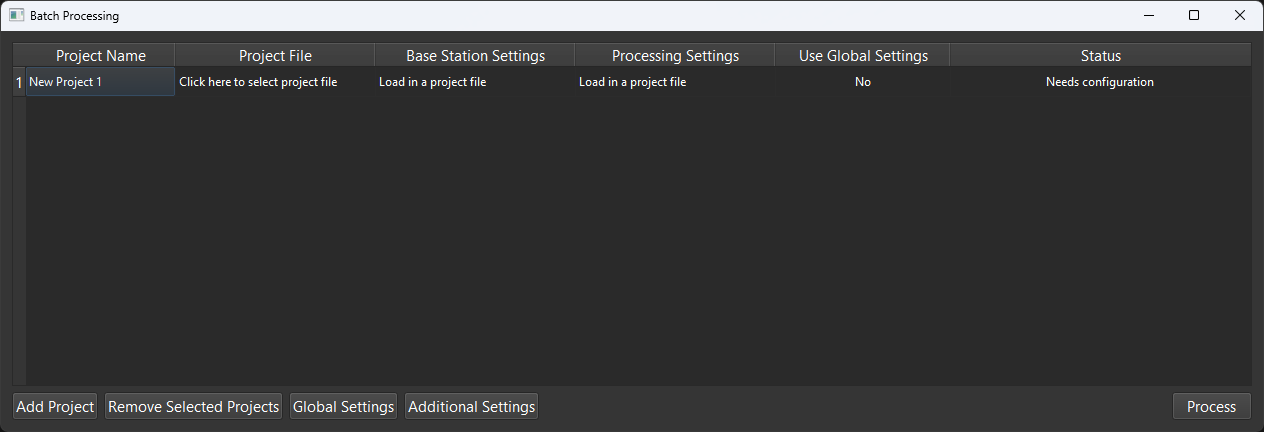
- Batch Processing: This is designed for ease of use and quick software processing for users with multiple datasets to process. It allows users to easily select their desired settings and final output formats, as well as finalization tools. Batch Processing window shown below.
- All settings main project settings from the software can be configured for a single project, saved, and applied to all loaded projects within Batch Processor.
- If needing an explanation for all dialogues and settings, please refer to the main window explanations that are given. Functionality is the same.
- After configuring a project, the user may select the save profile button to add to the list within the main configuration menu to select for all loaded projects.
- More information can be found in Default Batch Processing documentation.
- All settings main project settings from the software can be configured for a single project, saved, and applied to all loaded projects within Batch Processor.
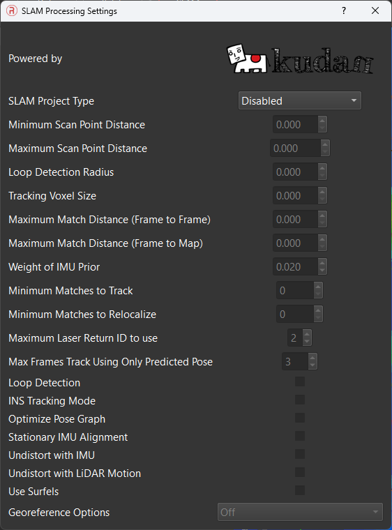
- SLAM Processing: This feature set is for utilizing SLAM features within the payload. Post processing can be performed through SLAM processing and is configured through the SLAM Processing dialogue. Further information can be found in the Default SLAM documentation.
Calibration #

- LiDAR Angular Offset: Opens a panel for adjusting the angular alignment between the LiDAR and payload reference frame, with immediate application to the cloud.
- LiDAR Linear Offset: Displays and allows adjustments to the linear offset between the LiDAR and IMU reference points in the LiDAR payload reference frame.
- Lasers: Displays a list of lasers and their calibration values, allowing for adjustments. Changes are immediately reflected in the point clouds.
- Camera Angular Offsets: Displays and allows adjustments to the angular alignment between the Camera and the payload reference frame.
- Camera Linear Offset: Displays and allows adjustments to the linear offset between the Camera and IMU reference points.
- Camera Calibration: Allows adjustments to camera image parameters to compensate for camera sensor and lens characteristics.
The settings regularly adjusted are:
- Focal Length – is measured in millimeters and is dependent on the camera lens that is used and camera manufacturer restrictions.
- Pixel flatness – is measured in ppm and is the difference between vertical dimension and horizontal dimension of a pixel. Enter in the pixel flatness as given by camera manufacturer (default value is 0).
- DistortNum – restricts the area of overlay for the camera images projected onto cloud points.
- DistortDen – restricts the area of overlay for the camera images projected onto cloud points.
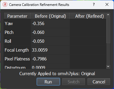
- Refine Camera Calibration: Allows for an automated adjustment to camera image parameters to compensate for camera sensor and lens characteristics. This will replace the factory calibration of the camera calibration but may prove beneficial on a per flight basis. User may switch between pre-loaded and refined values to observe differences.
- RESEPI Orientation: Displays the payload orientation in the vehicle’s reference frame. Changes should only be made if there was an initial setup error.
Settings #

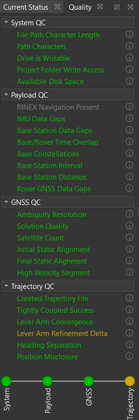
- Current Status: This button toggles the Status bar to show or hide. Also toggles Quality tab metrics used in post processing to show GNSS, INS, and Trajectory quality along with local system quality checks. Information and found values can be seen by clicking the info icon.
- System Theme: Provides options for customizing the interface appearance, with Regular and Dark themes available.
- Accent Color: Allows for changes to preset icon and UI colors with preset options or custom color input.
- UI Scale: Gives user custom control over UI items within the software. Range gives access to 0.75 to 1.5 scaling. Restart required.
- Available Threads: Gives user custom control over available thread access given to PCMasterPro. The default is Auto (4 threads) and will fit most scenarios and hardware configurations with exceptional speed improvements over past versions of software at a minor cost of memory. Increasing this value further increases projection and export speeds at the cost of slightly higher memory. Minimum value is 1 and maximum value is maximum available threads minus 4 to allow for other typical programs to run smoothly. Restart required.
- Visualizer Memory Budget: Allows users to enter in the desired max amount of memory available to PCMasterPro when populating the visualizer. If the point cloud exceeds the allowed memory limit, the loaded points will be decimated in order to meet the set limit. The memory limit may be exceeded in certain scenarios, but will allow for a higher performance overhead for other programs.
- PCMasterPro Licensing: Allows the entry and management of additional licenses for features like BayesMap Strip Align and SLAM. Displays active licenses, their types, expiration dates, and options for removal.
- Local License Manager: Manages the license required for post-processing navigation in PCMasterPro. Users can check the status, revoke, or enter a new license.
- About: Shows general information of software install when shown.
Strip Align #
As mentioned in the Export menu, PCMasterProGL includes the BayesMap Strip Align feature, which aligns point cloud strips for improved accuracy. This feature is most effective when used with surveyed Ground Control Points (GCPs) in the mission area.
Prerequisites: Ensure that you have a valid license for the Strip Align feature. Refer to the license section for more details.
Steps to Apply Strip Align:
Select Trajectory Paths: Choose the passes or paths you want to apply Strip Align to. For full mission alignment, use the Auto Select Trajectory option to generate the necessary individual strips. Note that Strip Align cannot be applied to a single strip and corresponding point cloud; multiple strips must be selected.
Upload Ground Control Points: Upload GCP locations using LiDAR Tools > Ground Control Points. You can use a text file to upload multiple GCP positions simultaneously. Accurate results with Strip Align depend on the availability of GCPs.
Export LAS File(s): Navigate to File > Export LAS File(s). Select the options to Export with/without Color and Apply Strip Align.
Completion: After processing, a confirmation message will appear at the bottom left of the window: “BayesMap Strip Align applied to Point Cloud with no Errors.”
Output: The final merged point cloud will be exported to the Clouds folder. Note that corrected LAS files will not be displayed in PCMasterPro; they will be directly exported to the Clouds folder.
To observe the entire process in practice, we suggest viewing the video recording below.