
RESEPI GEN-II System Overview #
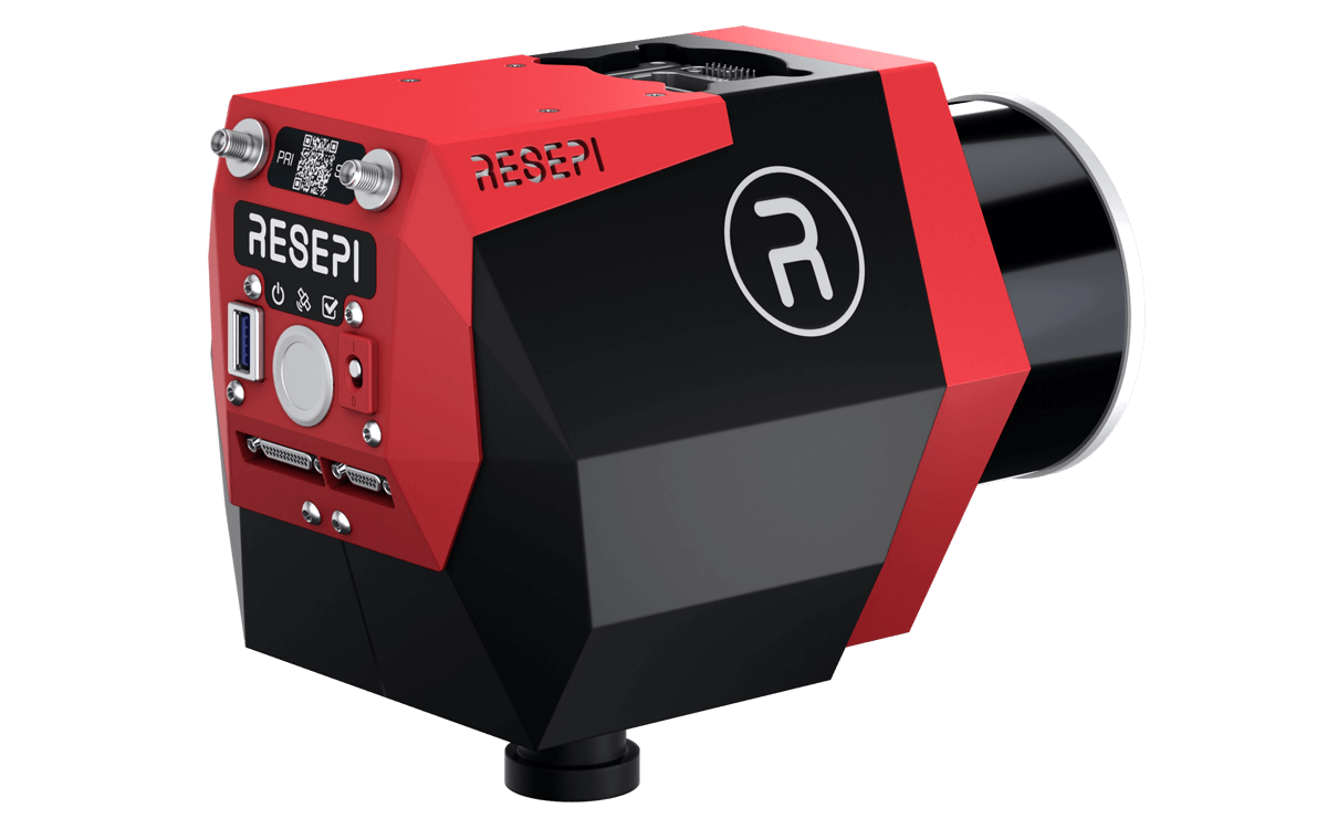
The RESEPI (Remote Sensing Payload Instrument) GEN-II represents the next generation in cutting-edge technology for mapping, surveying, and autonomous navigation. Building on the proven performance of its predecessor, it delivers enhanced capabilities, greater versatility, and seamless integration with multiple sensors, meeting the needs of professionals across industries.
System Components #
- GNSS + INS Integration
- Each unit includes a tightly coupled GNSS and IMU system for accurate position and orientation calculations. This data is used for georeferencing LiDAR and imagery in post-processing.
- Onboard Computer
- A rugged embedded computer handles real-time data capture, power management, and system control. It supports concurrent LiDAR and camera logging without the need for an external device.
- LiDAR Sensor Options
- XT32-M2X: Delivers superior point cloud accuracy for detailed mapping.
- Ouster OS1-64: Optimized for dense data capture. NDAA Compliant.
- RGB Camera
- 61MP Sony ILX-LR1: High resolution for colorization and photogrammetry.
- SnapFit™ Connectors for Rapid Deployment
- The new SnapFit™ connectors offer seamless power and data exchange, allowing for quick changes between platforms such as Gremsy, Skyport, Airpeak, FreeFly, Inspired Flight and more. This modular design makes the RESEPI GEN-II ideal for rapid deployment across various applications.
- Expanded Storage
- Comes equipped with a 512 GB internal SSD for increased storage capacity, facilitating smooth data acquisition and handling.
- GNSS Antennas
- All systems require a primary (PRI) GNSS antenna for positioning. Dual-antenna configurations provide a secondary (SEC) input for improved heading accuracy.
- Additional Peripherals
- Extended signal outputs allow the integration of multiple LiDARs, cameras, and other peripherals, providing flexibility for custom setups.
Power and Storage #
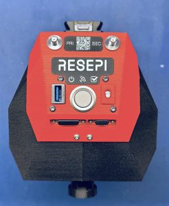
RESEPI GEN-II allows for easier control using a single multifunctional button coupled with a switch and 3 LEDs to indicate system status, as shown below.
- Power Input
- RESEPI operates from a 9–50V DC source and is compatible with standard connectors including XT60 and Binder. GEN-II units also support Ethernet and DJI Skyport interface options.
- Power button and Auto Power switch:
- Manual Mode:
- Start and stop the system with a single press of the power button.
- Single button press after starting up to start/stop data collection, without accessing the GUI.
- Long Press to power down the unit.
- Manual Mode:
- Auto Power Switch: Powers the system automatically when connected to a power source, ideal for mission-critical scenarios where minimal user intervention is required.
- LED Indicators:
- Power LED: Confirms that the system is powered on. Green when the unit is switched on.
- Status Check LED: Displays system operation status to monitor any faults.
- Green – System is working as intended. No errors detected.
- Red – Hardware error detected. Contact InertialLabs Support.
- Orange – Configuration error detected. Contact InertialLabs Support.
- GNSS LED: Provides real-time GNSS status for quick validation of signal availability and reception.
- Green – A valid GNSS fix was achieved.
- Red – No valid GNSS fix was achieved. Please ensure proper connections are made with the GNSS antenna.
- Orange – A valid GNSS fix with RTK differential corrections are being received.
- Data Management
- RESEPI GEN-II improves the storage capacity over the RESEPI LITE by introducing an internal SSD and allows to record larger missions than ever before and allows to access that data in multiple methods.
- Large Internal SSD: A 512 GB SSD that enables longer continuous data capture without interruptions.
- USB-A 3.0 Port: Facilitates faster direct data transfer from the SSD to a computer, utilizing an external USB stick. For example, SAMSUNG FIT Plus 3.1 USB Flash Drive.
- RESEPI GEN-II improves the storage capacity over the RESEPI LITE by introducing an internal SSD and allows to record larger missions than ever before and allows to access that data in multiple methods.
Connecting to the LiDAR Payload #
- Via Wi-Fi :
- Power On the Payload:
- Begin by powering on the payload. Press the power button to power up the unit.
- Connect to the Payload’s Wi-Fi:
- On your host computer (tablet, smartphone, or PC), open the Wi-Fi settings.
- Look for the unit’s wireless network, identifiable by its unique SSID on the device’s label, which will appear as “RESEPI – ######”.
- Connect to this network using the password “LidarAndINS” (also on device’s label). If this password does not work, contact your local vendor or customer support for assistance.
- Access the Web-GUI:
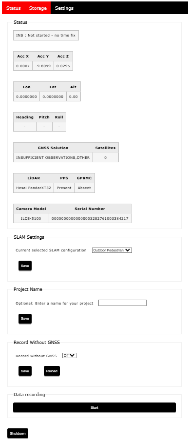
- The system is configured and controlled through a web-based interface accessible over Wi-Fi. Users can monitor GNSS/INS status, manage system settings, format storage, and control data logging without installing additional software.
- Open your preferred web browser.
- Enter the IP address (unquoted) “192.168.12.1” in the address bar.
- The LiDAR payload’s web-GUI will appear, as shown in below
- The system is configured and controlled through a web-based interface accessible over Wi-Fi. Users can monitor GNSS/INS status, manage system settings, format storage, and control data logging without installing additional software.
- Power On the Payload:
- Via Ethernet :
- Power On the Payload:
- Begin by connecting the ethernet cable to the payload. Do not connect both the barrel power and the ethernet on the computer side to the device. Only one of the ports should be used at once.
- Click the power button. If the auto-start button was switched on, the device would turn on automatically.
- Access the Web-GUI:
- Open your preferred web browser.
- Enter the IP address (unquoted) “192.168.13.1” in the address bar. This is different from the IP address of Wi-Fi based GUI.
- The LiDAR payload’s web-GUI will appear.
- Power On the Payload:
Downloading Data from the RESEPI GEN-II #
After completing a mission, downloading the dataset becomes a critical step. RESEPI GEN-II offers expanded options for data retrieval compared to RESEPI LITE, providing users with greater flexibility and convenience.
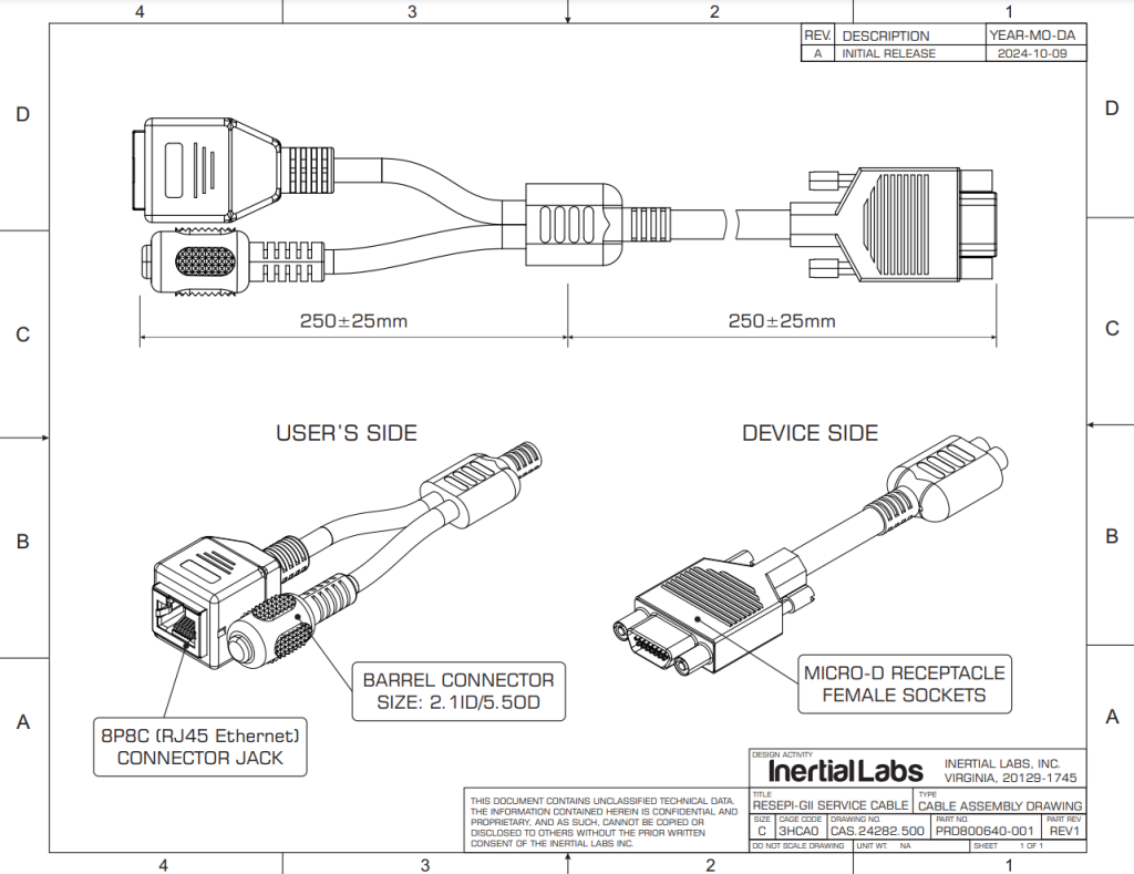
Since all of these methods would involve powering the RESEPI GEN-II, the user would need to power up RESEPI GEN-II using one of the two supported methods; either by connecting to the drone or platform providing power through SnapFit port, or by connecting the optional accessory cable (available from Inertial Labs, PN: PRD800640-001) to the rear panel of RESEPI GEN-II on XS1:380-015-113L001. This optional cable can be seen below. For more information or if desired for purchasing, please email sales@inertiallabs.com.
Via Wi-Fi:
- Connect to the RESEPI GUI.
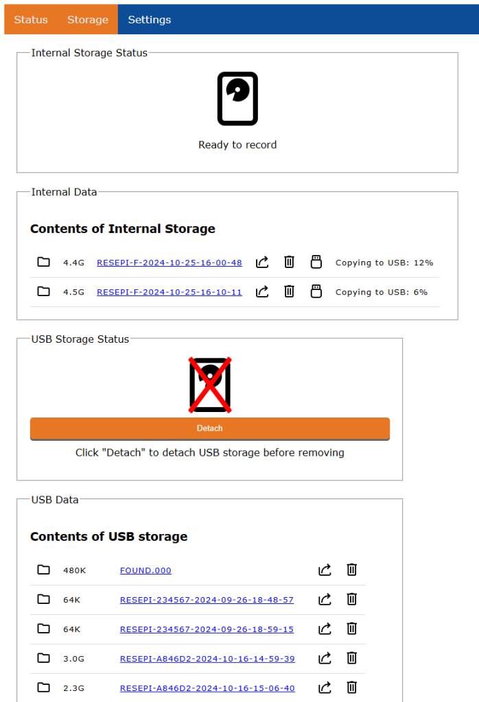
- Navigate to the Storage tab and select the mission you wish to export, as shown below.
- Press the Export (Share) button to initiate the download directly to the computer over Wifi.
Using an External USB Drive:
- Connect to the RESEPI GUI.
- Navigate to the Storage tab and select the mission you wish to export, as shown below.
- Insert the external USB drive into the RESEPI system.
- Press the Download (USB) button to transfer the data directly to the USB.
- A status percent indicator will show up next to the mission to show completion %.
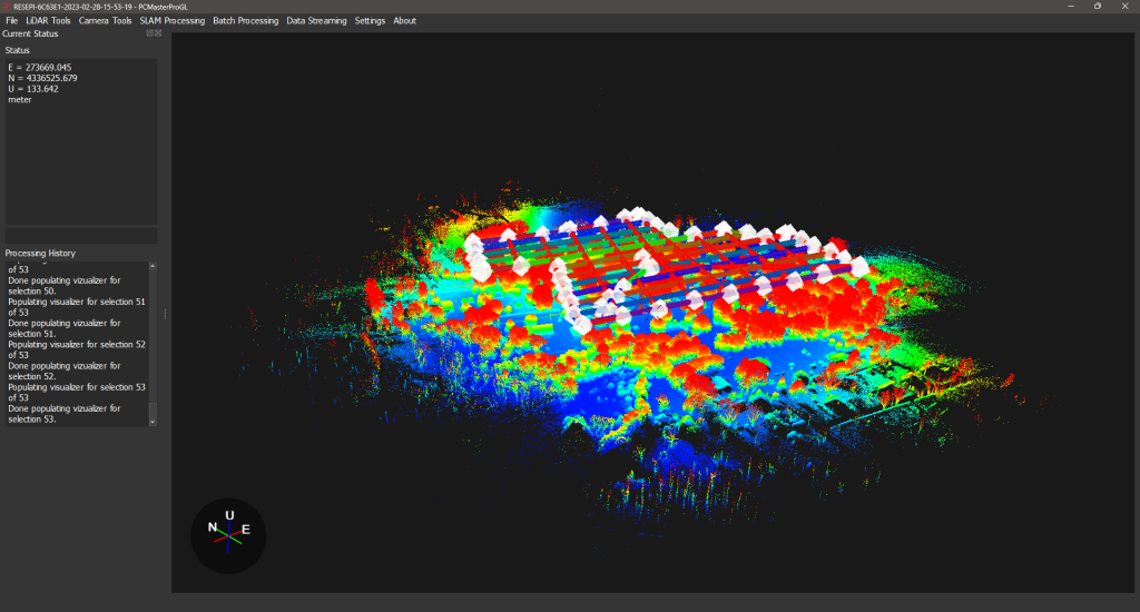
Data Processing Workflow #
RESEPI data is post-processed using PCMasterPro, which performs:
- Trajectory calculation using tightly coupled GNSS/IMU data
- LiDAR point cloud georeferencing
- Batch processing, SLAM algorithms, strip alignment, and more
- RGB image alignment and boresighting
- Coordinate transformations and export to various standard formats
Datasets can be further handled in third-party software such as TerraSolid, LiDAR360, Pix4D, and CloudCompare.
Extended Connectors for System Integration #
The RESEPI GEN-II features two extended connectors with detailed pinouts described below, enabling seamless integration with external systems and sensors. This capability allows users to feed aiding data directly into the INS, further enhancing positional accuracy to meet specific project needs.
Please ask the sales team if you need the ethernet compatible cable.
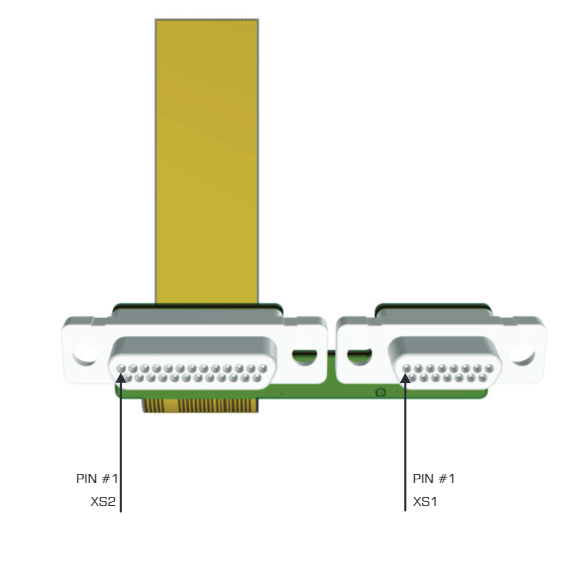
Pinout of the connectors #
| XS1:380-015-113L001 | |
| ETH2_B- | 1 |
| ETH2_B+ | 2 |
| ETH2_A- | 3 |
| ETH2_A+ | 4 |
| ETH2_D- | 5 |
| ETH2_D+ | 6 |
| ETH2_C- | 7 |
| ETH2_C+ | 8 |
| VSUP_REAR | 9 |
| VSUP_REAR | 10 |
| VSUP_REAR | 11 |
| VSUP_REAR | 12 |
| GROUND | 13 |
| GROUND | 14 |
| GROUND | 15 |
| XS2:380-025-113L001 | |
| COM4 (RS232_TX) | 1 |
| COM4 (RS232_RX) | 2 |
| COM1 (RS232_RX) | 3 |
| COM1 (RS232_TX) | 4 |
| 5V | 5 |
| GROUND | 6 |
| ENCODER (PHB) | 7 |
| ENCODER (PHA) | 8 |
| ENCODER (GROUND) | 9 |
| ENCODER (5V0) | 10 |
| UART0_TX | 11 |
| UART0_RX | 12 |
| 3V3 | 13 |
| ETH3_D- | 14 |
| ETH3_D+ | 15 |
| ETH3_C- | 16 |
| ETH3_C+ | 17 |
| ETH3_B- | 18 |
| ETH3_B+ | 19 |
| ETH3_A1 | 20 |
| ETH3_A+ | 21 |
| 1PPS (GPIO0_IO0B) | 22 |
| EV2 (GPIO2_IO04) | 23 |
| COM3 (RS232_RX) | 24 |
| COM3 (RS232_TX) | 25 |
RESEPI GEN-II Navigation Data Packet Structure #
To synchronize external sensors, the user can utilize COM1 on the rear panel of the device. By default, the following data is available:
COM1 Parameters:
- Data Rate: 200Hz
- Baud Rate: 921600
Data Types, in order:
0x02, // GPS INS Time, unsigned int, 8
0x03, // GPS IMU Time, unsigned int, 8
0x21, // Gyro data HR, int, 12
0x23, // Accelerometer data HR, int, 12
0x53, // Unit status word, word, 2
0x08, // Orientation angles HR (unsigned int, int, int), 12
0x11, // Position HR (int-8, int-8, int-4), 20
0x1B, // Velocity in ECEF coordinates, int, 12
0x36, // GNSS info short, byte, 2
0x3B, // Number of satellites used in solution, byte, 1
0x41, // New GPS, byte, 1
0x3C, // GPS week, word, 2
0x54, // INS solution status, byte, 1
0x04, // UTC, byte, 9
0x26, // Sensors bias, (sb, sb, sb, sb, sb, sb, byte), 7
0x57, // KF position covariance HR, word, 6
0x56, // KF heading covariance, byte, 1
0x58, // KF velocity covariance, byte, 3
0x5C, // KF pitch, roll covariance, word, 4
0x39 // GNSS Position or Velocity type, byte, 1