
Default PPK #
The post-processing kinematic (PPK) workflow requires an Inertial Explorer license and results in the best possible data quality, ensuring ideal conditions for further cloud analysis. For optimal results and quick processing times, input an estimation of the IMU to Antenna Offset into the RESEPI’s GUI before data acquisition.
Save these offsets once uploaded by navigating to Settings > Geometry within the GUI and clicking “Save” beneath the “IMU to Antenna Offset” fields.
The PPK workflow is designed for users who have purchased the LiDAR payload with the PPK Bundle powered by Inertial Explorer. This workflow can be used with MMS and RTK datasets, assuming the user has the required license and base station data. The Default PPK Full Workflow can be summarized into the following operations:
Activate the Inertial Explorer license using the Local License Manager.
- The license remains active on the machine until manually returned. If processing on a single machine, activate the license only once.
- Read more here.
Add base station file(s) from the hour of the flight to the “data” folder on the thumb drive.
Open the PPK PCMasterProGL project.
- If there is no “ppk.txt” already in the “ins” folder, the trajectory processor will automatically begin running.
Select desired portions of the trajectory and apply any desired filters.
Navigate to File > Export LAS File(s) and select the characteristics of your final cloud(s) (e.g., colorized, compressed, separate files per path).
Detailed Procedure: #
After finishing recording a dataset, remove the USB thumb drive from the payload and plug it into the PC used for data processing.
Copy the entire flight folder locally to the computer for faster processing speeds.
- If a custom project name was set through the “Status” page of the GUI, it will appear as a prefix to the automatically configured flight name stamped with UTC time. The generic naming convention for the dataset is as follows: RESEPI-AAAAAA-BBBB-CC-DD-EE-FF-GG
- AAAAAA: The device’s internally broadcasted Wi-Fi SSID.
- BBBB: The year that the data recording was initialized.
- CC: The month that the data recording was initialized.
- DD: The day of the month that the data recording was initialized.
- EE: The hour of the day (based on 24 hours) that the data recording was initialized.
- FF: The minute of the day that the data recording was initialized.
- GG: The second of the day that the data recording was initialized.
- If a custom project name was set through the “Status” page of the GUI, it will appear as a prefix to the automatically configured flight name stamped with UTC time. The generic naming convention for the dataset is as follows: RESEPI-AAAAAA-BBBB-CC-DD-EE-FF-GG
Open the folder containing the flight files.
Manually add the base station file(s) from the time of the flight to the “data” folder in the root folder locally on your computer.
Ensure the PPK license is checked in.
Double-click on the file labeled “ppk.pcmp”.
Wait for the “ppk.pcmp” project to initiate in PCMasterProGL and for all newly generated folders to populate in the root folder.
Confirm or modify the IMU to Antenna lever arm offsets when prompted. If saved to the web GUI prior to the flight, these values will be shown. PCMasterProGL will still calculate and refine its measurements whether offsets have been entered or not. Preset offsets can reduce processing time by providing an initial value.
PCMasterProGL will prompt for the “Base measurements file”. Navigate to the “data” folder and select the base station data.
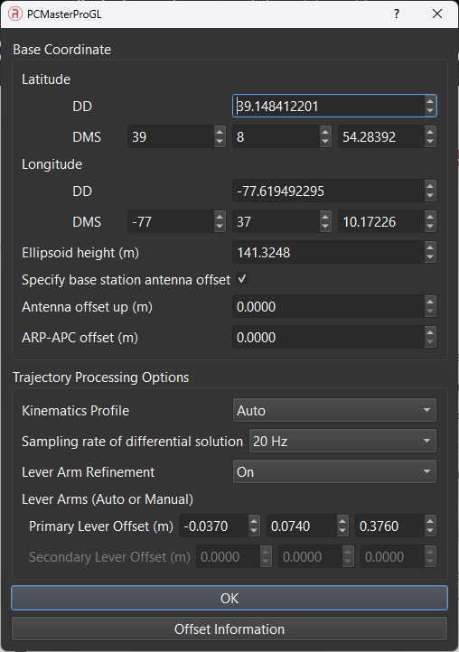
Confirm or modify the exact latitude, longitude, and ellipsoid height of the base station used for processing the dataset. Adjust the base station height if necessary, as shown in Figure 1.
- Choose the sampling rate of differential solution between 20Hz and 1 Hz or Auto. Auto is recommended as it chooses the base sampling rate with the best DGNSS quality.
PCMasterProGL will resample the base file and process the GNSS trajectory, displaying the East, North, and Vertical separation of the forward and reverse trajectories.
PCMasterProGL will correct the antenna lever arm by processing the loosely coupled IMU-GNSS position misclosure.
Calculate the attitude separation for heading, pitch, and roll, representing the difference between the forward and reverse processed trajectory values.
Once the PPK trajectory is calculated, PCMasterProGL will automatically load the trajectory and LiDAR files, populating the visualizer with the point cloud.
To select paths different from the default entire trajectory, remove the default path first under Data Selection > Paths. Then, select portions of the trajectory by right-clicking on a part of the trajectory and selecting “Start selection here”.
Find the location on the trajectory for the desired end point of that path, right-click, and select “Finish selection here”.
PCMasterProGL will load and display the geo-referenced laser points corresponding to this selected path.
Continue selecting starting and stopping points for as many path lines as desired. Manipulate which paths are viewed and/or exported using the options under Data Selection > Paths.
Adjust any cloud-specific settings using the Data Selection > Cloud Filters.
Proceed with exporting the final .las file.
To observe the entire process in practice, we suggest viewing the video recording below.
Base File Configuration Menu #
The base file configuration menu will pop up after a selection of base file as been made in Step 9. Users can configure and change Latitude and Longitude and Ellipsoidal height, which by default gets read from the header of the base file and usually contains averaged position. A surveyed position of the base station would yield better positioning results.
Position of the base station can be changed in either Degree Decimal or Degree Minute Seconds.
If the base file header contains antenna information, and that antenna type is present in the database, ARP-APC offset would be automatically populated.
Trajectory Processing Options
#
- Kinematics Profile – Users can decide between preset kinematics profiles that are optimized for certain scenarios with the INS. The default option is Auto, but users can overwrite this by selecting an option from the dropdown.
- Sampling rate of differential solution – Users can choose processing rate options between 20hz and 1 hz processing. In events of bad gnss observations, processing with 1hz can help.
- Lever Arm Refinement – Users can either choose to let PCMasterPro estimate a lever arm, if they aren’t sure of values (upto a mm level) based on GNSS and IMU observations, or if they have measured the lever arms, and can choose to force the measured lever arms instead of calculated ones.
Trajectory Selection #
If you have any difficulties with the selection of trajectory parts mentioned in Steps 16-17, we offer a video for your reference below.