
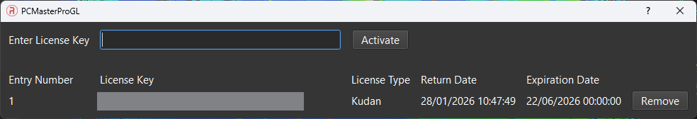
Activating RESEPI SLAM License: #
- Navigate to Settings > PCMasterPro Licensing.
- Enter the License Key and select “Activate” to check in the license, as below.
- The license status, including entry number, license key, license type, and expiration date, will be displayed.
- To check out the license, press the “Remove” button next to the corresponding entry.
Post-Processing SLAM Data with PCMasterPro #
Getting Started #
In order to run SLAM projects, SLAM must be turned on in PCMasterPro. Open PCMasterPro and select Toolkits > SLAM Processing. Choose the appropriate profile settings: indoor, outdoor, or custom, as shown below. Alternatively, if the user selected the preferred profile within the SLAM Settings window in the Status tab of the GUI prior to recording, a double click of the slam.pcmp file within the recording folder will automatically open PCMasterPro and start processing. This file is created in every dataset as of RESEPI LITE FW version 5.9.0.0 and RESEPI GEN-II FW 1.7.0.0 and will default to Outdoor settings if not configured prior to recording.
Notes:
- To revert to normal PPK processing, select “Disabled” in the SLAM settings before opening an existing project.
- A network connection is required only for validating the SLAM license key; it is not needed during cloud processing.
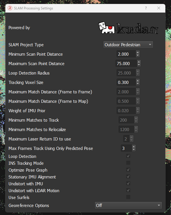
Available Processing Settings: #
- Min Matches to Relocalize & Min Matches to Track: Users should be able to change these settings based on the scan environment. If the scan is taken in an indoor region, features may be limited or sparse and thus a lower value is desired for this category in comparison to outdoor scenes. This relaxes the processing constraints and allows keyframes (each complete lidar revolution scan) to process easily with lower constraints on feature matching.
- Maximum Match distance frame to Map coefficient and Maximum match distance frame to frame: These settings adjust the scale factors for frame-to-frame translation and frame to map translation. The scan environment and application will require these parameters to be changed by the user. Note that as a rule of thumb the frame-to-frame scale factor is 4 times the frame to map scale factor for generating feasible results for all applications and scan regions.
- Recommended: (Default tuning values (confirmed from testing) are noted below)
- Small indoor room: frame to map SF – 0.1, frame to frame SF – 0.4
- Large indoor room: frame to map SF – 0.25, frame to frame SF – 1.0
- Small outdoor area: frame to map SF – 0.8, frame to frame SF – 3.2
- Large outdoor area: frame to map SF – 1, frame to frame SF – 4
- Recommended: (Default tuning values (confirmed from testing) are noted below)
- Minimum Point distance & Maximum Point distance: This setting controls thresholds for allowing the algorithm to know which points need to be accepted/utilized for processing in terms of how far the points to be scanned are from the device. For e.g. If you are in tighter regions, lower the minimum point distance to capture ranges from features that are within close proximity.
- Tracking voxel size: This setting will change based on the number of points being collected (area of scan region) and how accurate the user would want the final trajectory to be at the cost of compute time and power. Since the algorithm will be storing dense keyframes in the backend, the preferred voxel size becomes an important tradeoff to consider between processing time and accuracy. Using a smaller voxel size will increase the number of tracking points in each processing key frame but significantly increase processing time. Likewise, using a high voxel tracking size will reduce accuracy of the final point cloud (may introduce greater relative inaccuracy between features) but decrease processing time. It is recommended to use 0.1 m for indoor applications and 0.2-0.3m for outdoor applications.
- NOTE: A smaller voxel size will generally produce a more precise point cloud but at the cost of processing time.
- INS Tracking Mode: If the scanned motion path consists of jerky movements, rapid turns, and varying accelerations; one can enable the INS Tracking Mode checkbox before processing the cloud for enhancing the SLAM’s tracking performance to output a more accurate trajectory that considers non-linear motion more carefully.
- Undistort with LiDAR + IMU: If a static alignment during the IMU initialization phase was fairly stable then the user can enable “Undistort with IMU” and “Undistort with LiDAR Motion”. At times if the static alignment of the IMU may have been unsuccessful, the user can reprocess the cloud by just selecting “Undistort with LiDAR motion” only (and unchecking the stationary IMU alignment setting) which will ensure that the IMU readings aren’t used for motion blur correction.
- Use Surfels: Enabling this setting will allow the SLAM algorithm to examine planar surfaces (e.g. windows) in addition to continue tracking features using a voxelized map of the environment. This setting enhances the tracking ability of features within the environment and is useful to apply when processing indoor or urban region scans.
- “Weight of IMU Prior” – This value shouldn’t exceed 0.05 (0.02 by default), it is the weightage given to IMU pose estimates during regions in the scan when the LiDAR tracking state is determined to be less reliable by the internal SLAM sensor fusion algorithm.
- “Max Frames Track Using Only Predicted Pose” – An integer value is accepted for determining the maximum number of frames the SLAM algorithm should continue tracking using only a predicted position estimated by the IMU. This is useful for edge cases when the LiDAR tracking state is lost, e.g. a long corridor with no observable features.
- Maximum Laser Return ID to use: This field identifies the specific laser return type to use for SLAM processing from the LiDAR.
- For XT-32: This value should be set to 2 (default)
- For XT32-M2X: This value should be set to 3 (recommended)
- Georeference Option – To georeference the collected SLAM point cloud with calculated GNSS positions, switch this setting ON.
- The SLAM point cloud can only be georeferenced if the mission was collected with a GNSS antenna connected to the RESEPI unit during the mission. More information can be found here
Additional Application Notes:
- If the unit did not go through an adequate amount of IMU initialization time (i.e. Unit was not completely static or the time frame for the initialization time was under 8-10 seconds) then it is worth disabling the ‘Stationary IMU alignment’ setting and using only Undistort with LiDAR Motion.
- Other IMU Specific settings should ideally be utilized only when the default settings aren’t sufficient to build a high quality, dense point cloud.
Processing Data in PCMasterPro #
New Project from Project File:
- Method 1 – SLAM Settings configured in RESEPI GUI:
- Open the “slam” PCMP file in project folder by double clicking
- Processing will automatically start and run until completion
- Open the “slam” PCMP file in project folder by double clicking
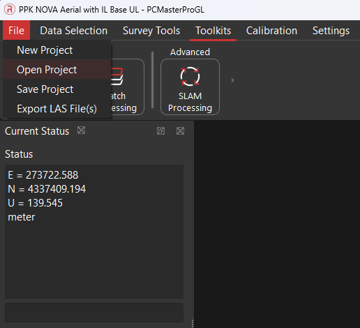
- Method 2 – Using Custom SLAM Settings or forgot to configure in RESEPI GUI:
- Click “SLAM Processing” -> “SLAM Processing Settings”, and select the type of SLAM project: “Indoor Pedestrian”, “Outdoor Pedestrian” or “Custom SLAM Settings” to process the SLAM data.
- Click “Open Project” and select the relevant RESEPI project folder, as shown below. Choose the “ppk” or “slam” PCMP file.
Note: If desired, user can also run SLAM by using .data files. This is done by selecting File -> “New” -> selecting all .data files instead of selecting the ppk.pcmp file.
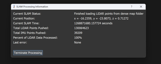
Processing SLAM Data:
- PCMasterPro will load the raw LiDAR and IMU data for processing. Monitor the process through the interface, as shown below.
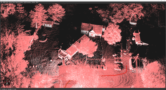
Viewing the Point Cloud:
- Once processing is complete, view the trajectory and point cloud in the local SLAM coordinate reference system, as shown below.
Subsection Extraction:
- Extract specific trajectory sections for detailed visualization by right-clicking on start and finish points.
Viewing and Exporting SLAM point cloud #
Cloud Filters:
- Once all the points have been loaded, the user can locate the available cloud filters under the Data Selection option to enhance the visualization experience. They can filter by distance, reflectivity, LiDAR point size, time and local trajectory (X, Y, Z) output.
Export Menu:
- If the user wishes to export the selected segment of the trajectory as a .LAS file, they can locate the “Export LAS File(s)” option under the “File” tab and export the cloud. Note: In this initial version of the SLAM tool, users will not be able to export colorized clouds. The user can also wish to export the cloud into multiple .las files if the file size is too large and there is need for segmentation.
- Users can locate SLAM exported clouds from PCMasterPro within the “clouds” subfolder of the main project’s directory.
Reprocess Trajectory:
- If the user wishes to reprocess the trajectory using different SLAM settings or process the open project as a PPK, then they will be able to do so using the “Reprocess Trajectory” option under the Data Selection tab.
- Note: To process as PPK, the user should first select the “Disabled” option under the Toolkits tab or select and configure a different SLAM settings profile prior to selecting the reprocess trajectory option.
- In order to use the trajectory pose information output by SLAM, users shall utilize the “true trajecory.txt” file that is generated in the “denseMap” subfolder within the main project’s directory.
To observe the entire process in practice, we suggest viewing the video recording below.