
Overview #
Determine Antenna Lever Arm offsets and input them into the IMU to Antenna Offset fields in the RESEPI or EchoONE GUI (GUI-Settings-Geometry-IMU to Antenna Offset). It is highly recommended that you use a dual antenna setup for the best possible trajectory. Please also ensure that the unit FW is v5.6.0.0 or newer.
Double check that the Vehicle to IMU Rotation offsets match the orientation of the RESEPI or EchoONE unit when mounted on the vehicle (GUI-Settings-Geometry-Vehicle to IMU Rotation). This step is very important as it will heavily impact whether your data can be processed or not.
Please also ensure the mission begins and ends in good GNSS environment with minimal overhead obstructions nearby. This is very important for mission processing.
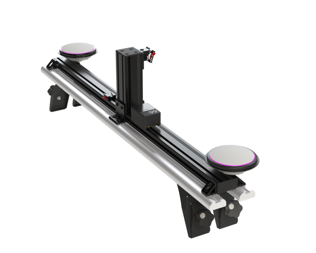
Inertial Labs Mobile Mapping Mount #
When utilizing the Inertial Labs dual-antenna Mobile Mapping Mount, users benefit from a pre-calibrated design with fixed lever arms for both GNSS antennas. This configuration eliminates the need for manual measurement or estimation of antenna positions relative to the inertial measurement unit (IMU), reducing setup time and improving system reliability.
To achieve the highest possible accuracy during post-processing, users should take advantage of this fixed lever arm setup. Within the processing software menu, there is an option to apply predefined lever arm values. It is strongly recommended to enable this option and force the use of these known lever arms. Doing so ensures that the spatial relationship between the antennas and the IMU is precisely accounted for, resulting in improved positioning and orientation accuracy—especially during high-dynamic maneuvers or in GNSS-challenged environments.
Lever Arm For Mobile Mount #
- That values are for Ultra LITE and LITE
Z Y X A1 0.118 0.111 0.603 A2 0.118 0.111 -0.603 - That values are for GEN-II – typical orientation is (180, 70, 0)
Z Y X A1 0.086 0.15 0.603 A2 0.086 0.15 -0.603
*These values are true for standard products shown on the lidarpayload.com website.
Operating Procedure #
Mount RESEPI or EchoONE Payload
- Properly mount the RESEPI or EchoONE payload to the vehicle.
Mount Antenna
- Ensure that the antenna(s) is/are securely and properly mounted on the vehicle in an area with good visibility of the sky.
Connect GNSS Cables
- Connect the GNSS cable to the primary antenna port (designated PRI or PRM).
- If applicable, connect the GNSS cable to the secondary antenna port (designated SEC).
Connect Power Cable
- Connect the power cable between the source and the RESEPI or EchoONE unit.
Power On RESEPI or EchoONE
- Turn on the RESEPI unit using the power button.
Connect to RESEPI or EchoONE via Wi-Fi
- Connect to the RESEPI or EchoONE unit via Wi-Fi.
- Wi-Fi SSID is located on the unit’s label.
- The password is “LidarAndINS”.
Verify GNSS Connection
- Check the GNSS connection in the RESEPI or EchoONE GUI. It should be a minimum of “Computed Single” (for PPK processing) or “Computed Narrow Float” (for RTK processing).
Check Satellite Count
- Ensure the number of satellites in the RESEPI or EchoONE GUI is greater than 10.
- Go to Settings-> INS Service
- Select On for Recording Secondary Antenna data.
Start Recording
- Begin recording by pressing the start button on the GUI or by pressing the power button once.
Initial Static Alignment
- Wait 1 minute for initial static alignment. (it is recommended that the initial alignment time be increased to 1 minute). This is configured in the RESEPI GUI.
- It is recommended that the vehicle be turned off during this time to minimize vibration.
Kinematic Alignment
- For the next 5 minutes, drive around with dynamic changes like heading changes, figure 8, turns and minor pitch and roll to simulate actual mission dynamics in near best GNSS environment.
Proceed with Drive Route
- Continue with the desired drive mission.
Final Kinematic Alignment
- After completing the drive route, for the next 5 minutes again, drive around with dynamic changes like heading changes, figure 8, turns and minor pitch and roll to simulate actual mission dynamics in near best GNSS environment.
Final Static Alignment
- Wait 1 minute for final static alignment and continue logging data during this period.
Stop Recording
- Stop recording by pressing the stop button on the GUI or by pressing the power button once.
Shut Down Device
- Shut down the device by pressing the Shutdown button on the GUI.